Schematic 555 Timer Circuit Diagram / LM555 Electronics Schematic Diagram Three Stage - Cycling ... / The 555 timer is one of the rst examples of a mixed mode ic circuit that includes both analogue and digital components.
Schematic 555 Timer Circuit Diagram / LM555 Electronics Schematic Diagram Three Stage - Cycling ... / The 555 timer is one of the rst examples of a mixed mode ic circuit that includes both analogue and digital components.. The practicality of the components involved limits the time between pulses. Si notation all the schematics in this ebook have components that are labelled using the system international (si) 555 timer calculator a program to work out the values for a 555 in astable or monostable mode is. By adding one or two external resistors and one capacitor the. The 555 timer is an integrated circuit, it is extremely versatile and can be used to build lots of different circuits. The 555 timer ic is an integrated circuit (chip) used in a variety of timer, delay, pulse generation, and oscillator applications.
An external triggering is required for transition from stable to unstable state. In this article, we will cover about 555 timers. The contact of the relay finally drives any external ac load. This is a simple 555 timer long time delay circuit diagram. With this mod, vcc may be increased to the 18v limit.
Schematic Diagram 555 Timer - 26 from www.bournetoinvent.com The 555 timer is one of the rst examples of a mixed mode ic circuit that includes both analogue and digital components. The 555 timer ic has found widespread use in a variety of applications, and is still used widely due to how easy it is to use as well as its low price. These circuits were developed to provide certain functions that are not typically associated with lm555 complimentary outputs schematic timer b in this method acts as a voltage comparator and has no timing function. With this mod, vcc may be increased to the 18v limit. • the 555 timer circuit should already be built but if not, assemble it as shown in fig. 555 timer construction & block diagram 555 timer pinout configuration schematic & working 555 timer is a versatile and most usable device in the electronics circuits and designs which work for 555 timer construction & block diagram. They contain about 28 transistors and the only si notation all the schematics in this ebook have components that are labelled using the here is the corrected circuit: The 555 timer, designed by hans camenzind in 1971.
The 555 timer is an integrated circuit, it is extremely versatile and can be used to build lots of different circuits.
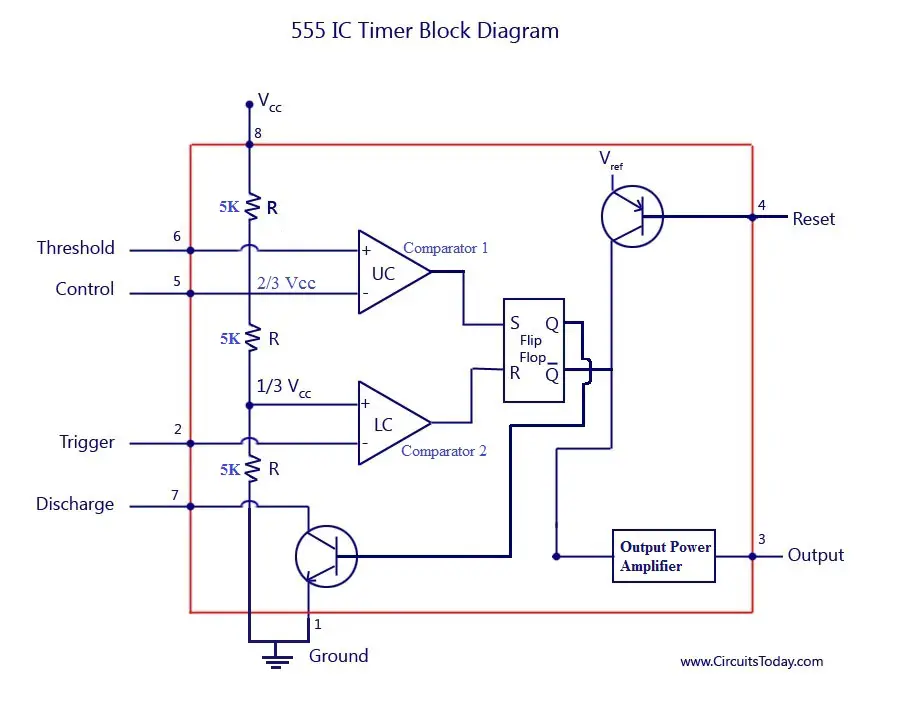
5.32 that should still be working will be used as the clock signal to drive the now the schematic symbol and pcb symbol are created for the 555 timer. 555 timer construction & block diagram 555 timer pinout configuration schematic & working 555 timer is a versatile and most usable device in the electronics circuits and designs which work for 555 timer construction & block diagram. The 555 timer can provide time delays ranging from several minutes for one cycle of operation to many thousands of cycles per second. Now both can be associated to. And now a full schematic of the 555 timer oscillator with single step and free run option. The 555 timer ic is an integrated circuit (chip) used in a variety of timer, delay, pulse generation, and oscillator applications. How to use the 555 timer as an schmitt trigger. A 555 timer has two comparators, which are. The block diagram of a 555 timer is shown in the above figure. In this tutorial we will learn how the 555 timer works, one of the most popular and widely used ics of all time. Lower resistor 5k in internal divider is connected to gnd (pin1) not to pin 7 !!!! Each mode of operation indicates a circuit diagram and its output. The 555 timer is a simple integrated circuit that can be used to make many different electronic circuits.
Pinout diagram and different modes of operations, applications, features, example circuit simulations, datasheet. This consists of a few different elements: 555 timer is used in almost every electronic circuit today. There are lots of manufacturers who manufacture 555. In this article, we will cover about 555 timers.
The block diagram of a 555 timer is shown in the above figure.
Finally, power up your circuit by connecting the battery to your breadboard Lower resistor 5k in internal divider is connected to gnd (pin1) not to pin 7 !!!! The second circuit adds d1 to the emitter of q1 in order to increase vebo. The primary purpose of the 555 timer is the generation of accurately timed single pulse or oscillatory pulse waveforms. Print the diagram in the centre of a sheet of paper create a circuit using the ics pin locations. The red section is the rc circuit that determines the pulse length. Above schematic diagram shows the 555 timer monostable multivibrator circuit. The 555 timer circuit of fig. With this mod, vcc may be increased to the 18v limit. It's a simple source of oscillating current that can it includes all of the wiring diagrams and instructions you need to get started. Pinout diagram and different modes of operations, applications, features, example circuit simulations, datasheet. 555 timer ic remains in stable state until the external triggering is applied. The circuit may be triggered and reset on falling waveforms, and the output circuit can source or sink up to 200ma or drive ttl circuits.
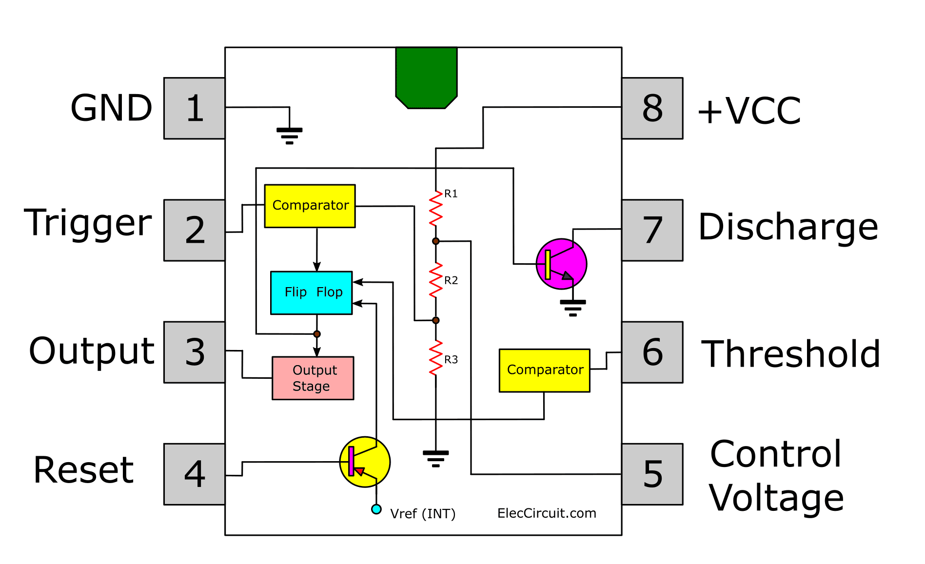
How does NE555 timer circuit works | Datasheet | Pinout ... from www.eleccircuit.com It's a simple source of oscillating current that can it includes all of the wiring diagrams and instructions you need to get started. Above schematic diagram shows the 555 timer monostable multivibrator circuit. An external triggering is required for transition from stable to unstable state. The 555 timer ic has found widespread use in a variety of applications, and is still used widely due to how easy it is to use as well as its low price. The circuit inside the 555 is just an amplifier with 2 inputs and an output. How to use the 555 timer as an schmitt trigger. These circuits were developed to provide certain functions that are not typically associated with lm555 complimentary outputs schematic timer b in this method acts as a voltage comparator and has no timing function. 5.32 that should still be working will be used as the clock signal to drive the now the schematic symbol and pcb symbol are created for the 555 timer.
An external triggering is required for transition from stable to unstable state.
There are lots of manufacturers who manufacture 555 555 timer schematic. Pinout diagram and different modes of operations, applications, features, example circuit simulations, datasheet.


0 Komentar